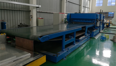
NC Feeder Features and Operating Procedures
Three-in-one Machine NC Servo Feeder
This machine features:
1. The collecting rack, leveling, feeding three machines in a machine, take up less space.
2. set optoelectronics, hydraulic, pneumatic in one, a high degree of automation.
3. the shelves are equipped with trolleys, the loading is safe and convenient.
Three-in-one Machine NC Servo Feeder Operation Procedures
Loading
1) Make sure all circuits, oil circuit, and gas circuit are connected and there is no problem. Turn on the power and put the operation mode in manual mode.
2) Press the "Retract" button to receive the minimum rack.
3) Open the pressure arm air pressure switch and point the arrow to "A", at which point the pressure arm is released.
4) Press the "Trolley Back" button to return the trolley to the end.
5) Place the coils vertically on the trolley, then press the "Trolley Ascent" or "Trolley Falling" button to make the center of the coil overlap with the center of the rack.
6) After adjusting the center of the coil, press the "Trolley Forward" button to let the rack pass through the inner ring of the coil and make the centerline of the material coincide with the centerline of the leveler as far as possible.
7) At this time, press the "rack extension" button to allow the feeder to tighten the inner ring of the coil.
8) Point the arrow of the pressure arm switch to "B" so that the pressure wheel of the pressure arm presses against the outer ring of the coil.
9) After confirming that there are no problems, the trolley will be retreated to the end and the loading is complete.
Feeding
1) Open the gas control valve of the feeding device, allow the feeding device to lift the supporting material, and then open the gas control valve of the pressure device to lift the pressure roller.
2) Relax in and out of the cylinder.
3) Pull one end of the roll and place it between the upper and lower rollers of the leveler.
4) Place the operation mode switch on the electric control box in manual mode.
5) Move the "Leveling Forward" button until the material completely extends out of the leveler.
6) Adjust the stopper wheel on both sides and lock it. Feeding is completed.
Note: The above operation must be performed in manual mode. The above buttons used in automatic mode are invalid.
Adjustment
1) When adjusting the correction effect, it is advisable to use a material about 1.5 meters long to be corrected for debugging.
2) The correction effect is one of the important indicators of the correction machine. The correction machine has simplified the correction and adjustment process to reflect the design idea of the machine with high efficiency and low labor intensity.
3) When adjusting the leveling roller, it should be noted that the left and right adjustment handwheels should be adjusted synchronously, and can be adjusted with reference to the scale, as shown below:
4) After the material to be processed is corrected to requirements, it can be sent to the coil for automatic production.
Feeding
Tuning test case
1) Start the straightening machine or material rack and slowly discharge the material.
2) Move the leveling wheel up or leveling wheel down button, adjust the gap between the upper and lower wheels, and finally use manual adjustment.
3) The role of pressure spring is to apply pressure to the upper roller, so that the upper roller can suppress the material, and the material is sent out, so the pressure should be based on the principle of the material will not slip. When the material thickness should be greater pressure.
4) After setting the feeding length, look at the actual situation and set the feeding speed accordingly. The relevant setting method will be described in detail later.
5) After the relevant parameters of the feeding are set, due to the reason of the number, the actual feeding length is not the same as the set value. Therefore, in the manual mode, press the feeding test, press, stroke, stamping, and adjust the feeding. The actual length.
6) When the tip of the guide pin in the mold enters the guide pin hole, it can be adjusted to loosen the screw until it touches the bearing of the loose bracket until the material is relaxed, and the screw nut is locked (If the air-releasing feeder is used, it should be adjusted. Relaxed angle, that is, about ±15° below dead)
7) Feeding start adjustment is adjusted by the rotating cam of the press. The so-called feeding start signal is to start the feed at which angle of the press crankshaft. The recommended angle of feeding the machine is 9 to 3 o'clock (240°-90°).
8) After the setting is completed, a single punch test mode should be used first, and then it can be continuously produced after adjustment.
 August 13, 2018The well-known metal stripping machine manufacturers in China, Rishbin won the title of National High-tech Enterprise. The metal slitting machine product line has full control of production...view
- November 22, 2018With the rapid development of the market, many industries have more and more strict requirements on product quality. In terms of high-speed slitting machine industry, due to higher and higher requirem...view
- January 24, 2019Overview of Round BladesMaterial selectionIn the steel slitting machine cutting industry, the blades are usually selected and selected according to the composition of the metal elements, as follows.A....view
- November 22, 2018Now the steel slitting line is becoming more and more popular, so you must know the relevant knowledge. The conveyor adopts the anti-static driving rubber wheel with concentricity and roundness <0....view
- August 29, 2018The numerically controlled cross shear machine can also be called a small-scale CNC shearing machine, and the English name is CNC horizontal shear machine equipment. CNC cross shears are classified cr...view
- August 29, 2018With the new and different technology days, we can feel that everything is starting automation, just to save time, effort, safety, and efficiency. All walks of life are taking the NC automation route....view